Catalog

Sectional garage sectional doors made of single-layer panels with torsion mechanism RSD02-SLP China

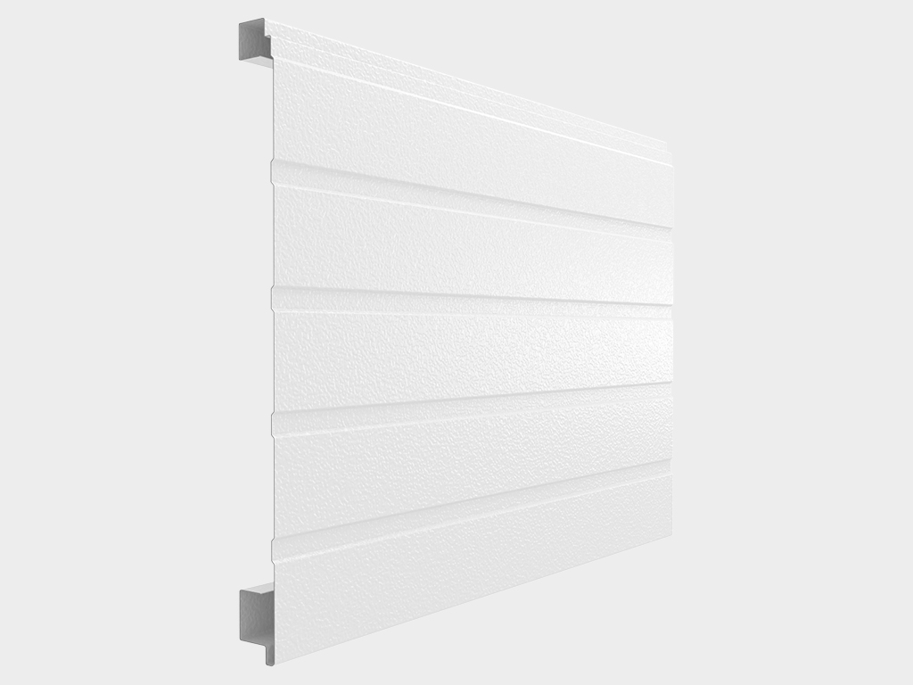
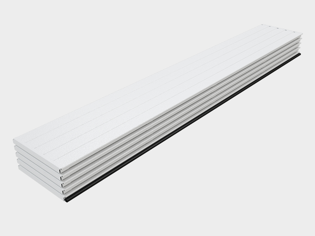
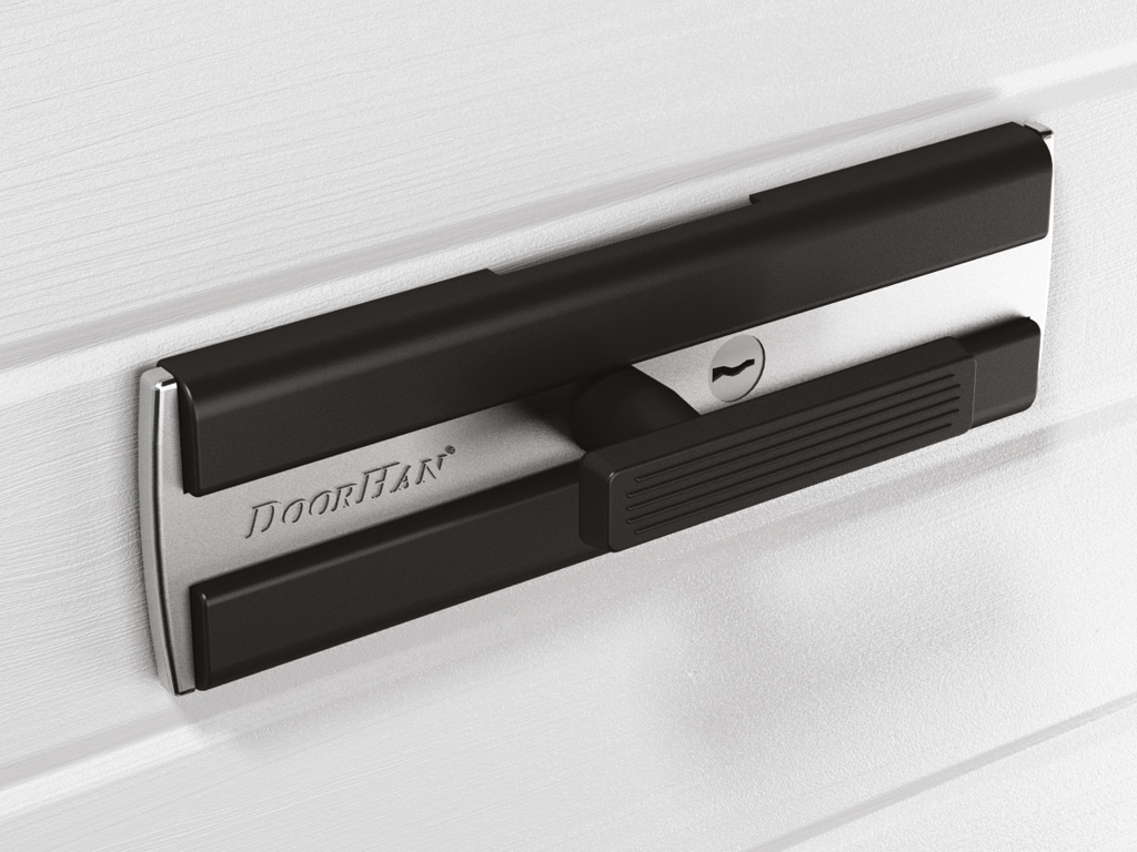
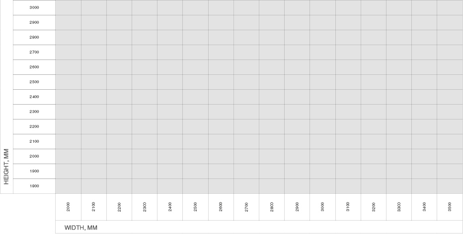
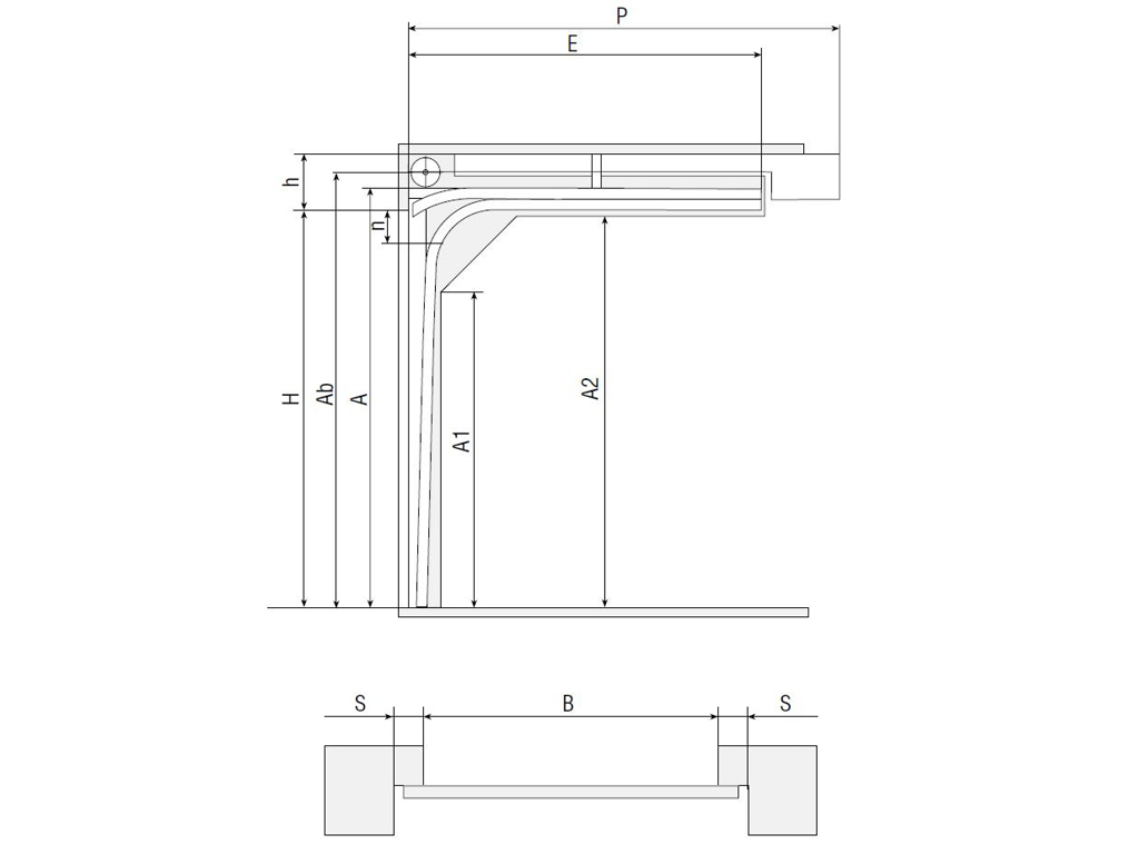
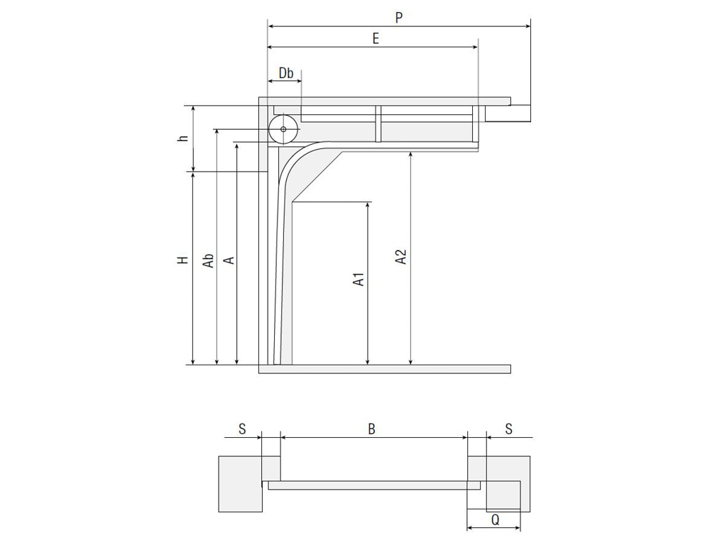
Sectional doors made from single-layer panels of the RSD02-SLP China series are designed for installation in small entrance openings. Such sectional doors are suitable for premises that do not require additional thermal insulation (covered parking lots, unheated garages, etc.). Sectional doors RSD02-SLP China can be installed in rooms with a lintel (distance from the top edge of the opening to the nearest obstacle or ceiling) from 160 mm and side distances (from the edge of the opening to the wall) from 120 mm, for openings with a width of 2 000 to 3 500 mm and height from 1 800 to 3 000 mm.
Application:
Advantages
Best price
The best price offer on the sectional door market.
Quick installation
Lightweight and simple design ensures extremely easy installation.
Rigid design
The reliable steel frame of the panels ensures the strength of the gate shield.
Best price
The best price offer on the sectional door market.
Quick installation
Lightweight and simple design ensures extremely easy installation.
Rigid design
The reliable steel frame of the panels ensures the strength of the gate shield.
Design
Panel design
Surface type
Colors of the front surfaces of the panels
D-line
D-line
Stucco (external)
Stucco (external)
Stucco (internal)
Stucco (internal)
External panel color — RAL 9003 (white)
Panel color inside: gray (ground)
Equipment
Standard
Optional
Canvas made of single-layer panels 40 mm thick with reinforcements.

Canvas made of single-layer panels 40 mm thick with reinforcements.

The guides have a simplified design and have all the perforations necessary for installation.

The guides have a simplified design and have all the perforations necessary for installation.

Torsion mechanism designed for 25 000 cycles. The durability of the gate design ensures that the door opens and closes effortlessly.

Torsion mechanism designed for 25 000 cycles. The durability of the gate design ensures that the door opens and closes effortlessly.

Box with installation kit, instructions and product data sheet.

Box with installation kit, instructions and product data sheet.

A mechanical lock allows you to block the door leaf in the closed position both from inside the room and from the street.

A mechanical lock allows you to block the door leaf in the closed position both from inside the room and from the street.

Technical description
Size Table
Opening Dimensions
Construction
Standard Construction
Specifications
Operating Conditions
Packaging
Parameters
Value
Opening height, mm
1 800–3 000
Opening width, mm
2 000–3 500
Headroom, mm
From 160 for low lift
Headroom, mm
From 350 for standard lift
Sideroom clearance, mm
From 120
  1. Gate leaf balancing system (spring-torsion mechanism)
  2. End U-shaped support bracket
  3. Guides for the door leaf
  4. Support with roller holder and roller
  5. Vertical stand
  6. Side cover
  7. Mounting bracket for vertical tracks
  8. Mounting bracket for angles
  9. Ceiling mounting system
  10. Upper support bracket
  11. Single layer panel reinforcement
  12. Single-layer panels
  13. Bottom corner bracket
  14. Bottom profile and seal
  15. Handle
  16. Inner loop

Low rise, drum at the front.

Low rise, drum at the front.

Symbol, parameter name Calculation formula
H, mm Opening height H
h, mm Headroom height h ≥ 160
B, mm Opening width B
A, mm Angle track height H + 54
Ab, mm Height of shaft axle and drum A + 59
A1, mm Vertical track height А - 543
A2, mm Horizontal track height А - 106
E, mm Horizontal track length Н + 315
S, mm Minimum side room clearance 120
P, mm Door opener position Н + 1 185
n, mm Clear opening 190 (without drive); 0...10 (with ceiling drive)
Standard lift.

Standard lift.

Symbol, parameter name Calculation formula
H, mm Opening height H
h, mm Headroom height R381: ≥ 420; R305: ≥ 350
B, mm Opening width B
A, mm Angle track height R381: H+235; R305:H+165
Ab, mm Height of shaft axle and drum A + 97
A1, mm Vertical track height R381: A - 580; R305: A - 490
A2, mm Horizontal track height А - 110
E, mm Horizontal track length R381: H+200; R305:H+250
Db, mm Torsion spring operation space 100
S, mm Minimum side room clearance 120
P, mm Door opener position Н + 1 060
Parameter Value Notes
Number of cycles 25 000
Force of manual opening and closing, N 150
Door leaf weight, kg/m² 8,5

1. Sections of the door leaf must move smoothly along the guides, and the door itself must be balanced, i.e., its weight must be compensated by the torque of the springs.

2. Manual opening and closing of the gate is carried out only with the help of a handle.

3. When opening and closing the gate manually, do not apply much force to it. Sudden jerks are unacceptable.

4. Make sure that people and animals are not in the area of the gate while it is operating.

5. It is strictly prohibited to move under the moving door leaf, as this can lead to injury.

6. Do not subject the gate to impacts or interfere with its free movement when opening and closing.

7. Do not expose the guides and rollers to contamination, as this can lead to disruption of smooth operation, and in the case of an electric drive, this can lead to its overload and failure.

8. Make sure that there are no foreign objects or debris in the opening while the blade is moving. Their presence can lead to skewing and jamming of the gate.

Packing in cardboard Packaging features
Description The guide system and panel of sectional doors have a rigid combined packaging made of cardboard and polystyrene foam, covered with stretch film; the complete set is packed in a corrugated cardboard box and sealed with packaging film; All packages are equipped with information stickers containing order data, as well as the company logo
Contents Five-layer cardboard, polystyrene foam, stretch film, tape
Width, mm 500–800
Height, mm 200–400
Length, mm 2 100–3 600
Gross weight, kg Up to 100
Number of items in the packaging Shield packaging — from 4 to 5 panels; package of guides — 1 guide system; packaging of components — box with complete set
Packing in cardboard box Packaging features
Length, mm 550
Additional Information print

It is recommended to store sandwich panels in their original packaging in a horizontal position on a flat surface for no more than 6 months from the date of production in closed warehouses or under a canopy. The panels must be protected from direct sunlight, precipitation and contamination.

Installation
Mounting Options
Checking Dimensional Details
Surface-mounted installation on the opening: the guide system is mounted on the walls and lintel on the inside of the opening.
  1. To take the necessary indicators, a tape measure and a building level are enough. All measurements are taken indoors. Each value must be measured at least at three points (in extreme positions and in the center).
  2. H is the height of the opening (distance from the floor to the top of the opening).
  3. B — opening width (distance from the left edge to the right edge of the opening).
  4. h — lintel (distance from the top of the opening to the obstacle) min 160 mm.
  5. b1/ b2 — left/right side distance (distance from the corresponding edge of the opening to the obstacle) min 120 mm.
  6. L is the depth of the room.
  7. When measuring H and B, the largest value is taken as the final size.
  8. When measuring h, b1, b2 and L, the smallest value is taken as the final size.
  9. The difference in floor level across the entire width of the opening should not exceed 10 mm. It is necessary to ensure that the mounting plane (walls and ceiling) is maintained. The base for installing the guide system must be monolithic and durable; if this is not available, additional edging or the formation of an opening with metal products is required.
Design
Panel design
D-line
D-line
Surface type
Stucco (external)
Stucco (external)
Stucco (internal)
Stucco (internal)
Colors of the front surfaces of the panels
External panel color — RAL 9003 (white)
Panel color inside: gray (ground)
Equipment
Standard
Canvas made of single-layer panels 40 mm thick with reinforcements.

Canvas made of single-layer panels 40 mm thick with reinforcements.

The guides have a simplified design and have all the perforations necessary for installation.

The guides have a simplified design and have all the perforations necessary for installation.

Torsion mechanism designed for 25 000 cycles. The durability of the gate design ensures that the door opens and closes effortlessly.

Torsion mechanism designed for 25 000 cycles. The durability of the gate design ensures that the door opens and closes effortlessly.

Box with installation kit, instructions and product data sheet.

Box with installation kit, instructions and product data sheet.

Optional
A mechanical lock allows you to block the door leaf in the closed position both from inside the room and from the street.

A mechanical lock allows you to block the door leaf in the closed position both from inside the room and from the street.

Technical description
Size Table
Parameters
Value
Opening height, mm
1 800–3 000
Opening width, mm
2 000–3 500
Headroom, mm
From 160 for low lift
Headroom, mm
From 350 for standard lift
Sideroom clearance, mm
From 120
Construction
  1. Gate leaf balancing system (spring-torsion mechanism)
  2. End U-shaped support bracket
  3. Guides for the door leaf
  4. Support with roller holder and roller
  5. Vertical stand
  6. Side cover
  7. Mounting bracket for vertical tracks
  8. Mounting bracket for angles
  9. Ceiling mounting system
  10. Upper support bracket
  11. Single layer panel reinforcement
  12. Single-layer panels
  13. Bottom corner bracket
  14. Bottom profile and seal
  15. Handle
  16. Inner loop
Standard Construction

Low rise, drum at the front.

Low rise, drum at the front.

Symbol, parameter name Calculation formula
H, mm Opening height H
h, mm Headroom height h ≥ 160
B, mm Opening width B
A, mm Angle track height H + 54
Ab, mm Height of shaft axle and drum A + 59
A1, mm Vertical track height А - 543
A2, mm Horizontal track height А - 106
E, mm Horizontal track length Н + 315
S, mm Minimum side room clearance 120
P, mm Door opener position Н + 1 185
n, mm Clear opening 190 (without drive); 0...10 (with ceiling drive)
Standard lift.

Standard lift.

Symbol, parameter name Calculation formula
H, mm Opening height H
h, mm Headroom height R381: ≥ 420; R305: ≥ 350
B, mm Opening width B
A, mm Angle track height R381: H+235; R305:H+165
Ab, mm Height of shaft axle and drum A + 97
A1, mm Vertical track height R381: A - 580; R305: A - 490
A2, mm Horizontal track height А - 110
E, mm Horizontal track length R381: H+200; R305:H+250
Db, mm Torsion spring operation space 100
S, mm Minimum side room clearance 120
P, mm Door opener position Н + 1 060
Specifications
Parameter Value Notes
Number of cycles 25 000
Force of manual opening and closing, N 150
Door leaf weight, kg/m² 8,5
Operating Conditions

1. Sections of the door leaf must move smoothly along the guides, and the door itself must be balanced, i.e., its weight must be compensated by the torque of the springs.

2. Manual opening and closing of the gate is carried out only with the help of a handle.

3. When opening and closing the gate manually, do not apply much force to it. Sudden jerks are unacceptable.

4. Make sure that people and animals are not in the area of the gate while it is operating.

5. It is strictly prohibited to move under the moving door leaf, as this can lead to injury.

6. Do not subject the gate to impacts or interfere with its free movement when opening and closing.

7. Do not expose the guides and rollers to contamination, as this can lead to disruption of smooth operation, and in the case of an electric drive, this can lead to its overload and failure.

8. Make sure that there are no foreign objects or debris in the opening while the blade is moving. Their presence can lead to skewing and jamming of the gate.

Packaging
Packing in cardboard Packaging features
Description The guide system and panel of sectional doors have a rigid combined packaging made of cardboard and polystyrene foam, covered with stretch film; the complete set is packed in a corrugated cardboard box and sealed with packaging film; All packages are equipped with information stickers containing order data, as well as the company logo
Contents Five-layer cardboard, polystyrene foam, stretch film, tape
Width, mm 500–800
Height, mm 200–400
Length, mm 2 100–3 600
Gross weight, kg Up to 100
Number of items in the packaging Shield packaging — from 4 to 5 panels; package of guides — 1 guide system; packaging of components — box with complete set
Packing in cardboard box Packaging features
Length, mm 550
Additional Information

It is recommended to store sandwich panels in their original packaging in a horizontal position on a flat surface for no more than 6 months from the date of production in closed warehouses or under a canopy. The panels must be protected from direct sunlight, precipitation and contamination.

Installation
Mounting Options
Surface-mounted installation on the opening: the guide system is mounted on the walls and lintel on the inside of the opening.
Checking Dimensional Details
  1. To take the necessary indicators, a tape measure and a building level are enough. All measurements are taken indoors. Each value must be measured at least at three points (in extreme positions and in the center).
  2. H is the height of the opening (distance from the floor to the top of the opening).
  3. B — opening width (distance from the left edge to the right edge of the opening).
  4. h — lintel (distance from the top of the opening to the obstacle) min 160 mm.
  5. b1/ b2 — left/right side distance (distance from the corresponding edge of the opening to the obstacle) min 120 mm.
  6. L is the depth of the room.
  7. When measuring H and B, the largest value is taken as the final size.
  8. When measuring h, b1, b2 and L, the smallest value is taken as the final size.
  9. The difference in floor level across the entire width of the opening should not exceed 10 mm. It is necessary to ensure that the mounting plane (walls and ceiling) is maintained. The base for installing the guide system must be monolithic and durable; if this is not available, additional edging or the formation of an opening with metal products is required.
Checkout
Managers of the company will answer all
questions by phone: